企业私有网络架构运维
使用模拟器构建局域网
需求分析
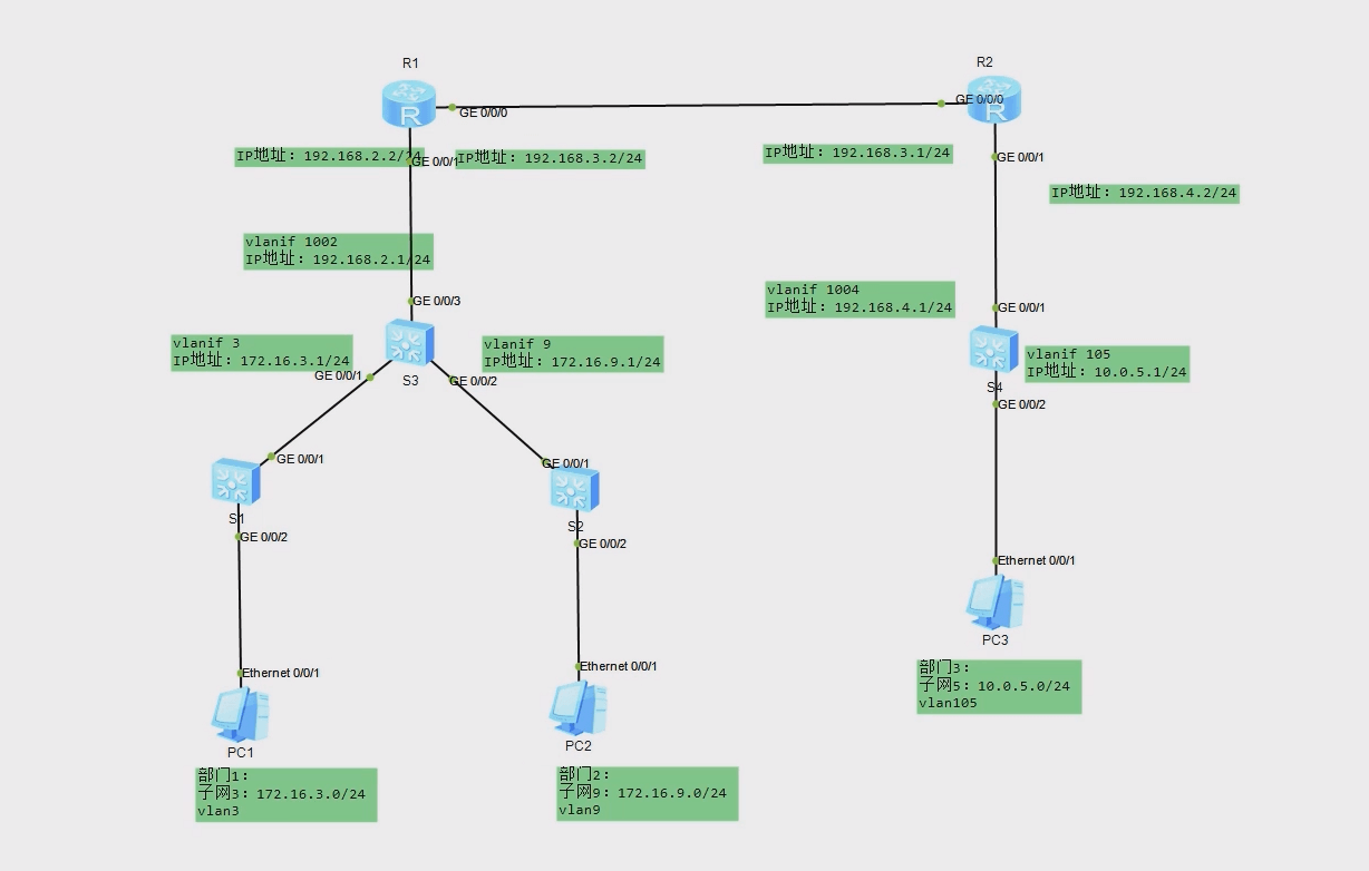
两个部门各使用一台交换机相连,然后连接到总交换机,再通过路由器与外网以及其他部门网络相连。为了控制网络上的广播风暴,增加网络的安全性,在交换机上需要设置VLAN,在路由器与交换机之间需要设置动态路由OSPF协议。
拓扑规划
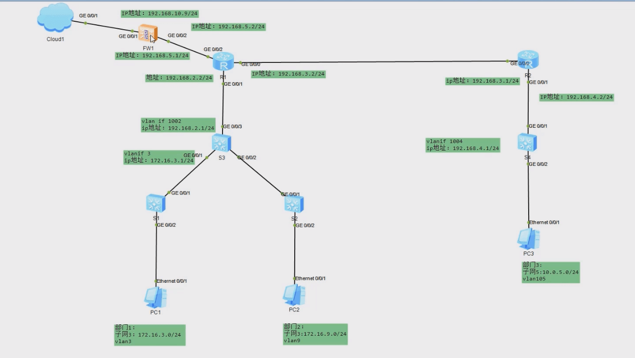
地点1 包括部门1和部门2;地点2包括部门3;
部门1网络为子网3:172.16.3.0/24,对应VLAN3;
部门2网络为子网9:172.16.9.0/24,对应VLAN9;
部门1、部门2的计算机分别通过交换机S1、S2接入,然后通过总交换机S3互联,S3连接路由器R1,R1通过R2与地点2的部门3网络子网5:10.0.0.0/24相连
1
2
3
4
5
6
7
8
9
10
11
12
| <Huawei>system-view
[Huawei]sysname S1
[S1]vlan batch 3 9 1002
[S1]interface GigabitEthernet 0/0/2
[S1-GigabitEthernet0/0/2]port link-type access
[S1-GigabitEthernet0/0/2]port default vlan 3
[S1-GigabitEthernet0/0/2]quit
[S1]interface GigabitEthernet 0/0/1
[S1-GigabitEthernet0/0/1]port link-type trunk
[S1-GigabitEthernet0/0/1]port trunk allow-pass vlan 3 9 1002
|
1
2
3
4
5
6
7
8
9
10
11
12
| <Huawei>system-view
[Huawei]sysname S2
[S2]vlan batch 3 9 1002
[S2]interface GigabitEthernet 0/0/2
[S2-GigabitEthernet0/0/2]port link-type access
[S2-GigabitEthernet0/0/2]port default vlan 9
[S2-GigabitEthernet0/0/2]quit
[S2]interface GigabitEthernet 0/0/1
[S2-GigabitEthernet0/0/1]port link-type trunk
[S2-GigabitEthernet0/0/1]port trunk allow-pass vlan 3 9 1002
|
1
2
3
4
5
6
7
8
9
10
11
12
13
14
15
16
17
18
19
20
21
22
23
24
25
26
27
28
29
30
31
32
33
34
35
36
37
38
39
40
41
42
43
44
45
46
47
| <Huawei>system-view
[Huawei]sysname S3
[S3]vlan batch 3 9 1002
[S3]interface GigabitEthernet 0/0/1
[S3-GigabitEthernet0/0/1]port link-type trunk
[S3-GigabitEthernet0/0/1]port trunk allow-pass vlan 3 9 1002
[S3-GigabitEthernet0/0/1]quit
[S3]interface GigabitEthernet 0/0/2
[S3-GigabitEthernet0/0/2]port link-type trunk
[S3-GigabitEthernet0/0/2]port trunk allow-pass vlan 3 9 1002
[S3-GigabitEthernet0/0/2]quit
[S3]interface GigabitEthernet 0/0/3
[S3-GigabitEthernet0/0/3]port link-type access
[S3-GigabitEthernet0/0/3]port default vlan 1002
[S3-GigabitEthernet0/0/3]quit
[S3]dhcp enable # 开启dhcp
[S3]interface Vlanif 3
[S3-Vlanif3]ip address 172.16.3.1 24
[S3-Vlanif3]quit
[S3]interface Vlanif 9
[S3-Vlanif9]ip address 172.16.9.1 24
[S3-Vlanif9]dhcp select global # 配置dhcp为全局
[S3-Vlanif9]quit
[S3]interface Vlanif 1002
[S3-Vlanif1002]ip address 192.168.2.1 24
[S3-Vlanif1002]quit
[S3]ospf 1
[S3-ospf-1]area 0
[S3-ospf-1-area-0.0.0.0]network 192.168.2.0 0.0.0.255
[S3-ospf-1-area-0.0.0.0]network 172.16.3.0 0.0.0.255
[S3-ospf-1-area-0.0.0.0]network 172.16.9.0 0.0.0.255
[S3-ospf-1-area-0.0.0.0]quit
[S3-ospf-1]quit
[S3]ip pool vlan9 # 配置DHCP地址池
[S3-ip-pool-vlan9]gateway-list 172.16.9.1
[S3-ip-pool-vlan9]network 172.16.9.0 mask 255.255.255.0
[S3-ip-pool-vlan9]lease day 3 # 租期为3天
[S3-ip-pool-vlan9]dns-list 8.8.8.8
|
1
2
3
4
5
6
7
8
9
10
11
12
13
14
15
16
17
18
19
20
21
22
23
24
25
26
| <Huawei>system-view
[Huawei]sysname S4
[S4]vlan batch 105 1004
[S4]interface GigabitEthernet 0/0/1
[S4-GigabitEthernet0/0/1]port link-type access
[S4-GigabitEthernet0/0/1]port default vlan 1004
[S4-GigabitEthernet0/0/1]quit
[S4]interface GigabitEthernet 0/0/2
[S4-GigabitEthernet0/0/2]port link-type access
[S4-GigabitEthernet0/0/2]port default vlan 105
[S4-GigabitEthernet0/0/2]quit
[S4]interface Vlanif 1004
[S4-Vlanif1004]ip address 192.168.4.1 24
[S4-Vlanif1004]quit
[S4]interface Vlanif 105
[S4-Vlanif105]ip address 10.0.5.1 24
[S4-Vlanif105]quit
[S4]ospf 1
[S4-ospf-1]area 0
[S4-ospf-1-area-0.0.0.0]network 192.168.4.0 0.0.0.255
[S4-ospf-1-area-0.0.0.0]network 10.0.5.0 0.0.0.255
|
1
2
3
4
5
6
7
8
9
10
11
12
13
14
15
| <Huawei>system-view
[Huawei]sysname R1
[R1]interface GigabitEthernet 0/0/1
[R1-GigabitEthernet0/0/1]ip address 192.168.2.2 24
[R1-GigabitEthernet0/0/1]quit
[R1]interface GigabitEthernet 0/0/0
[R1-GigabitEthernet0/0/0]ip address 192.168.3.2 24
[R1-GigabitEthernet0/0/0]quit
[R1]ospf 1
[R1-ospf-1]area 0
[R1-ospf-1-area-0.0.0.0]network 192.168.3.0 0.0.0.255
[R1-ospf-1-area-0.0.0.0]network 192.168.2.0 0.0.0.255
|
1
2
3
4
5
6
7
8
9
10
11
12
13
14
15
| <Huawei>system-view
[Huawei]sysname R2
[R2]interface GigabitEthernet 0/0/1
[R2-GigabitEthernet0/0/1]ip address 192.168.4.2 24
[R2-GigabitEthernet0/0/1]quit
[R2]interface GigabitEthernet 0/0/0
[R2-GigabitEthernet0/0/0]ip address 192.168.3.1 24
[R2-GigabitEthernet0/0/0]quit
[R2]ospf 1
[R2-ospf-1]area 0
[R2-ospf-1-area-0.0.0.0]network 192.168.3.0 0.0.0.255
[R2-ospf-1-area-0.0.0.0]network 192.168.4.0 0.0.0.255
|
配置部门1
IP:172.16.3.2
网关:172.16.3.1
配置部门2
dhcp
ipconfig命令
配置部门3
IP:10.0.5.2
网关:10.0.5.1
PC之间相互连通即为成功
使用模拟器接入互联网
架构分析
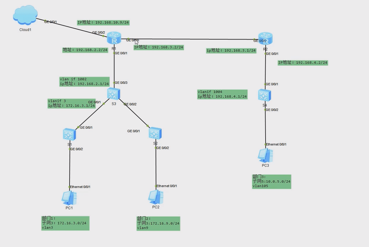
在以构建完成的小型局域网中,将网络接入互联网,局域网中实现各个网段互联互通,通过总路由器连接至互联网,在总路由器中添加默认路由策略,并通过动态路由协议分发给其他设备进行学习
规划拓扑
由总路由设置默认路由访问网络,并通过ospf下发默认路由。通过配置Cloud设备,将局域网与物理网卡进行联通,通过物理机虚拟网卡模拟联网,使物理机可以访问局域网中各部门PC机
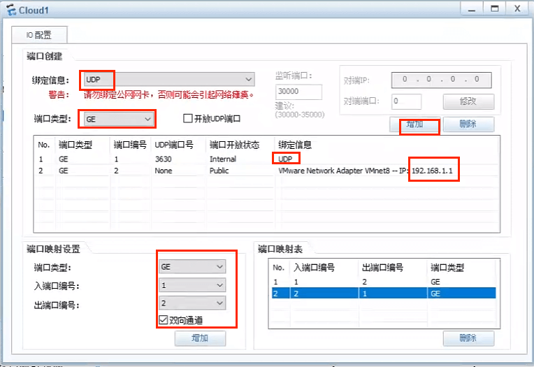
Cloud配置
R1
1
2
3
4
5
6
7
8
9
10
11
12
13
14
15
| <R1>system-view
# 网段根据Cloud里添加的网段设置
[R1]interface GigabitEthernet 0/0/2
[R1-GigabitEthernet0/0/2]ip address 192.168.1.9 24
[R1-GigabitEthernet0/0/2]quit
[R1]ip route-static 0.0.0.0 0 192.168.1.1
[R1]ospf 1
# always:始终播发默认路由
# cost:OSPF默认成本价值
# type:默认路由的OSPF指标类型(链路状态类型)
[R1-ospf-1]default-route-advertise always cost 200 type 1
[R1-ospf-1]quit
[R1]quit
|
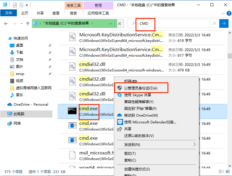
1
2
3
4
5
6
7
8
| C:\WINDOWS\system32>route add 172.16.3.0 mask 255.255.255.0 192.168.1.9
操作完成!
C:\WINDOWS\system32>route add 172.16.9.0 mask 255.255.255.0 192.168.1.9
操作完成!
C:\WINDOWS\system32>route add 10.0.5.0 mask 255.255.255.0 192.168.1.9
操作完成!
|
1
2
3
4
5
6
7
8
9
10
11
12
13
14
15
16
17
18
19
20
21
22
23
24
25
26
27
28
29
30
31
32
33
34
35
36
37
38
| C:\Users\Administrator>ping 172.16.3.2
正在 Ping 172.16.3.2 具有 32 字节的数据:
来自 172.16.3.2 的回复: 字节=32 时间=128ms TTL=126
来自 172.16.3.2 的回复: 字节=32 时间=65ms TTL=126
来自 172.16.3.2 的回复: 字节=32 时间=62ms TTL=126
来自 172.16.3.2 的回复: 字节=32 时间=55ms TTL=126
172.16.3.2 的 Ping 统计信息:
数据包: 已发送 = 4,已接收 = 4,丢失 = 0 (0% 丢失),
往返行程的估计时间(以毫秒为单位):
最短 = 55ms,最长 = 128ms,平均 = 77ms
C:\Users\Administrator>ping 172.16.9.254
正在 Ping 172.16.9.254 具有 32 字节的数据:
请求超时。
来自 172.16.9.254 的回复: 字节=32 时间=54ms TTL=126
来自 172.16.9.254 的回复: 字节=32 时间=46ms TTL=126
来自 172.16.9.254 的回复: 字节=32 时间=64ms TTL=126
172.16.9.254 的 Ping 统计信息:
数据包: 已发送 = 4,已接收 = 3,丢失 = 1 (25% 丢失),
往返行程的估计时间(以毫秒为单位):
最短 = 46ms,最长 = 64ms,平均 = 54ms
C:\Users\Administrator>ping 10.0.5.2
正在 Ping 10.0.5.2 具有 32 字节的数据:
来自 10.0.5.2 的回复: 字节=32 时间=79ms TTL=125
来自 10.0.5.2 的回复: 字节=32 时间=37ms TTL=125
来自 10.0.5.2 的回复: 字节=32 时间=59ms TTL=125
来自 10.0.5.2 的回复: 字节=32 时间=43ms TTL=125
10.0.5.2 的 Ping 统计信息:
数据包: 已发送 = 4,已接收 = 4,丢失 = 0 (0% 丢失),
往返行程的估计时间(以毫秒为单位):
最短 = 37ms,最长 = 79ms,平均 = 54ms
|
使用模拟器配置网络安全
案例目标
(1) 通过组网设计,掌握小型网络的组建、防火墙策略设置,对小型网络所使用的防火墙功能进行分析。
(2) 综合运用路由、防火墙安全规则、NAT 相关技术。
(3) 综合运用 NAT、防火墙规则配置局域网实现访问互联网,通过 OSPF 动态路由协议下发默认路由,实现小型网络与互联网通信。
案例分析
1.架构分析
(1) 需求分析
在已构建完成的小型局域网中,内网和互联网已实现互联通信,为增加内网访问外网安全性,在总路由器与外网之间添加访问防火墙,设置防火墙访问策略,限制内网与外网通信规则。防火墙设置动态路由协议,自动学习内网中路由策略。
(2) 环境要求
引用实战案例 2.1 的环境,配置虚拟网卡的计算机,华为 eNSP 模拟软件,构建完成的小型局域网络。
2.规划拓扑
(1) 拓扑描述
配置路由器与防火墙之间互联地址为 192.168.5.2/24,在路由器 OSPF 中发布与防墙互联网段。
配置防火墙与路由器互联地址为 192.168.5.1/24。配置与外网通信地址为 192.168.10.9/24,设置访问外网默认路由。配置内网访问外网 NAT 规则,保护内网地址。设置访问策略,部门1、部门 2 设置可以访问外网,部门3 设置为不能访问外网。
(2) 拓扑图
注意:此节是在实战案例最初构建局域网的环境上添加配置,防火墙使用 USG5500,路由器使用AR2220。
1
2
3
4
5
6
7
8
9
10
11
12
13
14
15
16
17
18
19
20
21
22
23
24
25
26
27
28
29
30
31
32
33
34
35
36
37
38
39
40
41
42
43
44
45
46
| <SRG>system-view
[SRG]firewall zone trust # 指示信任区域
[SRG-zone-trust]add interface GigabitEthernet 0/0/2
[SRG-zone-trust]quit
[SRG]firewall zone untrust # 指示不信任区域
[SRG-zone-untrust]add interface GigabitEthernet 0/0/1
[SRG-zone-untrust]quit
[SRG]interface GigabitEthernet 0/0/2
[SRG-GigabitEthernet0/0/2]ip address 192.168.5.1 24
[SRG-GigabitEthernet0/0/2]quit
[SRG]interface GigabitEthernet 0/0/1
[SRG-GigabitEthernet0/0/1]ip address 192.168.1.9 24
[SRG-GigabitEthernet0/0/1]quit
[SRG]ip route-static 0.0.0.0 0 192.168.1.1
# 指定安全区域(信任到不信任)之间配置出口安全策略
[SRG]policy interzone trust untrust outbound
# 指定策略id
[SRG-policy-interzone-trust-untrust-outbound]policy 0
# 指定操作(允许)
[SRG-policy-interzone-trust-untrust-outbound-0]action permit
# 指定源IP的网段(允许该网段)
[SRG-policy-interzone-trust-untrust-outbound-0]policy source 172.16.0.0 0.0.255.255
[SRG-policy-interzone-trust-untrust-outbound-0]quit
[SRG-policy-interzone-trust-untrust-outbound]quit
# 指定NAT策略:信任到不信任区域间出口配置
[SRG]nat-policy interzone trust untrust outbound
[SRG-nat-policy-interzone-trust-untrust-outbound]policy 1
# 指示已配置源NAT操作(基于源IP进行NAT转换)
[SRG-nat-policy-interzone-trust-untrust-outbound-1]action source-nat
[SRG-nat-policy-interzone-trust-untrust-outbound-1]policy source 172.16.0.0 0.0.255.255
[SRG-nat-policy-interzone-trust-untrust-outbound-1]easy-ip GigabitEthernet 0/0/1
[SRG-nat-policy-interzone-trust-untrust-outbound-1]quit
[SRG-nat-policy-interzone-trust-untrust-outbound]quit
[SRG]ospf 1
[SRG-ospf-1]area 0
[SRG-ospf-1-area-0.0.0.0]network 192.168.5.0 0.0.0.255
[SRG-ospf-1-area-0.0.0.0]quit
[SRG-ospf-1]default-route-advertise always cost 200 type 1
|
1
2
3
4
5
6
7
8
9
| <R1>system-view
[R1]interface GigabitEthernet 0/0/2
[R1-GigabitEthernet0/0/2]ip address 192.168.5.2 24
[R1-GigabitEthernet0/0/2]quit
[R1]ospf 1
[R1-ospf-1]area 0
[R1-ospf-1-area-0.0.0.0]network 192.168.5.0 0.0.0.255
|
使用模拟器配置无线网络
案例目标
(1)通过组网设计,掌握小型网络的组建、无线AC 控制器的配置,对网络使用无线设备范围、无线认证和信道进行分析。
(2)综合运用路由、防火墙安全规则、NAT 和无线AC 控制器
(3)通过使用无线AC 控制器对网络中的无线AP 进行管理,设置无线规则和认证策略,配置 DHCP 地址池,对无线AP 和通过AP 连接的设置进行动态地址分配。
案例分析
1.架构分析
(1)需求分析
对于小型局域网中,对于接入设备的需求,需要在局域网中部署无线网络,通过无线控制器AC管理网络中所有的无线AP 设备,下发无线配置信息。无线网络发布 2.4G和5G信号,满足不同设备的连接使用。
(2)环境要求
配置虚拟网卡的计算机,华为 eNSP.模拟软件。
2.规划拓扑
(1)拓扑描述
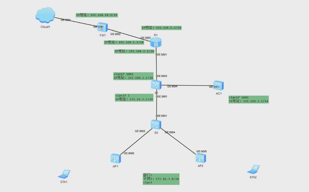
防火墙连接外网网卡地址为 192.168.1.9/24,路由器与核心交换机通联地址为192.168.2.0/24。防火墙安全规则只允许网络中无线网络中地址可以访问外网。
配置路由器与防火墙之间连接地址为 192.168.5.0/24 网段,配置与交换机互联地址为192.168.2.2/24。
核心交换机配置 vlan3 为连接无线网络设备,网关地址为 172.16.3.1/24,配置vlan1002为连接路由器,IP 地址为 192.168.2.1/24。
AC控制器管理地址为 192.168.3.1/24,设置 vlan1003 为 AC和AP 之间管理 VLAN,配置DHCP 地址池,使AP 可以自动获取管理地址。
(2)拓扑图
注意防火培使用 USG5500路由器使用AR2220,AC使用AC6005,AP 使用AP2050。
1
2
3
4
5
6
7
8
9
10
11
12
13
14
15
16
17
18
19
20
21
| <Huawei>system-view
[Huawei]sysname S2
[S2]vlan batch 3 1003
[S2]interface GigabitEthernet 0/0/3
[S2-GigabitEthernet0/0/3]port link-type trunk
# 指定接口默认VLAN 1003
[S2-GigabitEthernet0/0/3]port trunk pvid vlan 1003
[S2-GigabitEthernet0/0/3]port trunk allow-pass vlan 3 1003
[S2-GigabitEthernet0/0/3]quit
[S2]interface GigabitEthernet 0/0/4
[S2-GigabitEthernet0/0/4]port link-type trunk
[S2-GigabitEthernet0/0/4]port trunk pvid vlan 1003
[S2-GigabitEthernet0/0/4]port trunk allow-pass vlan 3 1003
[S2-GigabitEthernet0/0/4]quit
[S2]interface GigabitEthernet 0/0/1
[S2-GigabitEthernet0/0/1]port link-type trunk
[S2-GigabitEthernet0/0/1]port trunk allow-pass vlan 3 1003
|
1
2
3
4
5
6
7
8
9
10
11
12
13
14
15
16
17
18
19
20
21
22
23
24
25
26
27
28
29
30
31
32
33
34
| <Huawei>system-view
[Huawei]sysname S1
[S1]vlan batch 3 1002 1003
[S1]interface GigabitEthernet 0/0/1
[S1-GigabitEthernet0/0/1]port link-type trunk
[S1-GigabitEthernet0/0/1]port trunk allow-pass vlan 3 1003
[S1-GigabitEthernet0/0/1]quit
[S1]interface GigabitEthernet 0/0/4
[S1-GigabitEthernet0/0/4]port link-type trunk
[S1-GigabitEthernet0/0/4]port trunk allow-pass vlan 3 1003
[S1-GigabitEthernet0/0/4]quit
[S1]interface GigabitEthernet 0/0/3
[S1-GigabitEthernet0/0/3]port link-type access
[S1-GigabitEthernet0/0/3]port default vlan 1002
[S1-GigabitEthernet0/0/3]quit
[S1]dhcp enable
[S1]interface Vlanif 3
[S1-Vlanif3]ip address 172.16.3.1 24
# 选择接口服务器池,就是把添加的IP作为地址池下发
[S1-Vlanif3]dhcp select interface
[S1-Vlanif3]dhcp server dns-list 114.114.114.114 223.5.5.5
[S1-Vlanif3]quit
[S1]interface Vlanif 1002
[S1-Vlanif1002]ip address 192.168.2.1 24
[S1-Vlanif1002]quit
[S1]ip route-static 0.0.0.0 0 192.168.2.2
|
1
2
3
4
5
6
7
8
9
10
11
12
13
| <Huawei>system-view
[Huawei]sysname R1
[R1]interface GigabitEthernet 0/0/1
[R1-GigabitEthernet0/0/1]ip address 192.168.2.2 24
[R1-GigabitEthernet0/0/1]quit
[R1]interface GigabitEthernet 0/0/2
[R1-GigabitEthernet0/0/2]ip address 192.168.5.2 24
[R1-GigabitEthernet0/0/2]quit
[R1]ip route-static 0.0.0.0 0 192.168.5.1
[R1]ip route-static 172.16.3.0 255.255.255.0 192.168.2.1
|
1
2
3
4
5
6
7
8
9
10
11
12
13
14
15
16
17
18
19
20
21
22
23
24
25
26
27
28
29
30
31
32
33
| <SRG>system-view
[SRG]firewall zone trust
[SRG-zone-trust]add interface GigabitEthernet 0/0/2
[SRG-zone-trust]quit
[SRG]firewall zone untrust
[SRG-zone-untrust]add interface GigabitEthernet 0/0/1
[SRG-zone-untrust]quit
[SRG]interface GigabitEthernet 0/0/2
[SRG-GigabitEthernet0/0/2]ip address 192.168.5.1 24
[SRG-GigabitEthernet0/0/2]quit
[SRG]interface GigabitEthernet 0/0/1
[SRG-GigabitEthernet0/0/1]ip address 192.168.1.9 24
[SRG-GigabitEthernet0/0/1]quit
[SRG]ip route-static 0.0.0.0 0 192.168.1.1
[SRG]ip route-static 172.16.3.0 24 192.168.5.2
[SRG]policy interzone trust untrust outbound
[SRG-policy-interzone-trust-untrust-outbound]policy 0
[SRG-policy-interzone-trust-untrust-outbound-0]action permit
[SRG-policy-interzone-trust-untrust-outbound-0]policy source 172.16.3.0 0.0.0.255
[SRG-policy-interzone-trust-untrust-outbound-0]quit
[SRG-policy-interzone-trust-untrust-outbound]quit
[SRG]nat-policy interzone trust untrust outbound
[SRG-nat-policy-interzone-trust-untrust-outbound]policy 1
[SRG-nat-policy-interzone-trust-untrust-outbound-1]action source-nat 172.16.3
[SRG-nat-policy-interzone-trust-untrust-outbound-1]policy source 172.16.3.0 0.0.0.255
[SRG-nat-policy-interzone-trust-untrust-outbound-1]easy-ip GigabitEthernet 0/0/1
|
1
2
3
4
5
6
7
8
9
10
11
12
13
14
15
16
17
18
19
20
21
22
23
24
25
26
27
28
29
30
31
32
33
34
35
36
37
38
39
40
41
42
43
44
45
46
47
48
49
50
51
52
53
54
55
56
57
58
59
60
61
62
63
64
65
66
67
68
69
70
71
72
73
74
| <AC6005>system-view
[AC6005]sysname AC
[AC]vlan batch 3 1003
[AC]interface GigabitEthernet 0/0/1
[AC-GigabitEthernet0/0/1]port link-type trunk
[AC-GigabitEthernet0/0/1]port trunk allow-pass vlan 3 1003
[AC-GigabitEthernet0/0/1]quit
[AC]dhcp enable
[AC]interface Vlanif 1003
[AC-Vlanif1003]ip address 192.168.3.1 24
[AC-Vlanif1003]dhcp select interface
[AC-Vlanif1003]quit
# 无线局域网设置
[AC]wlan
# 创建AP组命令为ap-group1
[AC-wlan-view]ap-group name ap-group1
# 启用规则:默认(初始化)
[AC-wlan-ap-group-ap-group1]regulatory-domain-profile default
[AC-wlan-ap-group-ap-group1]quit
[AC-wlan-view]quit
# 通过capwap协议确定AC管理VLAN为1003
[AC]capwap source interface Vlanif 1003
[AC]wlan
# 认证模式:MAC地址认证
[AC-wlan-view]ap auth-mode mac-auth
# mac地址从AP上用命令display arp获取
[AC-wlan-view]ap-id 0 ap-mac 00e0-fcca-6d30
# 给第一个AP命名
[AC-wlan-ap-0]ap-name area_1
# 把AP加入组中
[AC-wlan-ap-0]ap-group ap-group1
[AC-wlan-ap-0]quit
[AC-wlan-view]ap-id 1 ap-mac 00e0-fc8c-2420
[AC-wlan-ap-1]ap-name area_2
[AC-wlan-ap-1]ap-group ap-group1
# 查看AP信息
[AC]display ap all
# 安全模板设置,模板命名为ssid_name
[AC-wlan-view]security-profile name ssid_name
# 加密模式wpa-wpa2 psk,加密方式aes,密码a1234567
[AC-wlan-sec-prof-ssid_name]security wpa-wpa2 psk pass-phrase a1234567 aes
[AC-wlan-sec-prof-ssid_name]quit
# 设置无线局域网名字
[AC-wlan-view]ssid-profile name ssid_name
[AC-wlan-ssid-prof-ssid_name]ssid ssid_name
[AC-wlan-ssid-prof-ssid_name]quit
# 虚拟AP模板,把模板绑定在一起方便应用
[AC-wlan-view]vap-profile name ssid_name
# 默认方式(本地直接转发)可有可无
[AC-wlan-vap-prof-ssid_name]forward-mode direct-forward
# 指明业务VLAN
[AC-wlan-vap-prof-ssid_name]service-vlan vlan-id 3
[AC-wlan-vap-prof-ssid_name]security-profile ssid_name
[AC-wlan-vap-prof-ssid_name]ssid-profile ssid_name
[AC-wlan-vap-prof-ssid_name]quit
# 进入组中应用虚拟AP模板
[AC-wlan-view]ap-group name ap-group1
# 把虚拟AP模板应用在wlan下的设备0和设备1
[AC-wlan-ap-group-ap-group1]vap-profile ssid_name wlan 1 radio 0
[AC-wlan-ap-group-ap-group1]vap-profile ssid_name wlan 1 radio 1
|
- 测试笔记本连上网后是否能ping通192.168.1.1
使用模拟器配置数据中心网络
案例目标
(1)通过组网设计,掌握数据中心网络的组建、设备的主备,对数据中心所需求的高可用网络架构进行分析。
(2)综合运用端口聚合、MSTP 和VRRP 相关技术
(3)综合使用 MSTP 和VRRP 实现网络设备的主备和路余灾备,可以自动切换备份链路。
案例分析
1架构分析
(1)需求分析
由于接入备份的需要,用户部署了冗余链路。几余备份链路的存在导致出现环网,可能会引起广播风暴和 MAC 地址表项被破坏。
用户希望在有冗余备份链路的同时消除网络中的环路,在一条上行链路断开时,流量能切换到另外一条上行链路转发,还能合理利用网络带宽。
(2)环境要求
配置虚拟网卡的计算机,华为 eNSP 模拟软件。
2规划拓扑
(1)拓扑描述
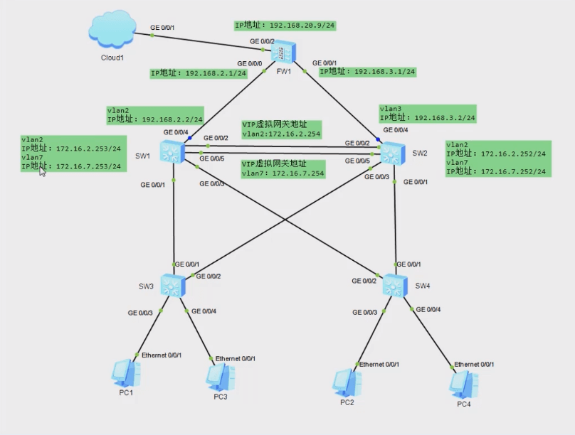
MSTP 可阻塞二层网络中的几余链路,将网络修剪成树状,达到消除环路的目的。同时在SW1和SW2 上配置VRRP,PC1 以SW1 为默认网关接入Intermet,sw2 作为备份网关;PC3以sW2为默认网关接入 Internet,SW1 作为备份网关,以实现可靠性及流量的负载分
SW1 交换机:配置 vlan2 地址为 172.16.2.253/24,配置 vla7 地址为 172.16.7.253/24。
SW2 交换机:配置 vlan2 地址为 172.16.2.252/24,配置 vla7 地址为 172.16.7.252/24。VRRP配置 vlan2 用户网络虚拟网关为 172.162.254,配置 vlan7 用户网络虚拟网关为172.16.7.254。
(2)拓扑图
注意:防火持使用 USG5500。
1
2
3
4
5
6
7
8
9
10
11
12
13
14
15
16
17
18
19
20
21
22
23
24
25
26
27
28
29
30
31
32
33
34
35
36
37
38
39
40
41
42
43
44
45
46
| <SRG>system-view
[SRG]interface GigabitEthernet 0/0/0
[SRG-GigabitEthernet0/0/0]ip address 192.168.2.1 24
[SRG-GigabitEthernet0/0/0]quit
[SRG]interface GigabitEthernet 0/0/1
[SRG-GigabitEthernet0/0/1]ip address 192.168.3.1 24
[SRG-GigabitEthernet0/0/1]quit
[SRG]interface GigabitEthernet 0/0/2
[SRG-GigabitEthernet0/0/2]ip address 192.168.1.9 24
[SRG-GigabitEthernet0/0/2]quit
[SRG]firewall zone trust
[SRG-zone-trust]add interface GigabitEthernet 0/0/0
[SRG-zone-trust]add interface GigabitEthernet 0/0/1
[SRG-zone-trust]quit
[SRG]firewall zone untrust
[SRG-zone-untrust]add interface GigabitEthernet 0/0/2
[SRG-zone-untrust]quit
[SRG]policy interzone trust untrust outbound
[SRG-policy-interzone-trust-untrust-outbound]policy 0
[SRG-policy-interzone-trust-untrust-outbound-0]action permit
[SRG-policy-interzone-trust-untrust-outbound-0]policy source 172.16.2.0 0.0.0.255
[SRG-policy-interzone-trust-untrust-outbound-0]policy source 172.16.7.0 0.0.0.255
[SRG-policy-interzone-trust-untrust-outbound-0]quit
[SRG-policy-interzone-trust-untrust-outbound]quit
[SRG]nat-policy interzone trust untrust outbound
[SRG-nat-policy-interzone-trust-untrust-outbound]policy 1
[SRG-nat-policy-interzone-trust-untrust-outbound-1]action source-nat
[SRG-nat-policy-interzone-trust-untrust-outbound-1]policy source 172.16.2.0 0.0.0.255
[SRG-nat-policy-interzone-trust-untrust-outbound-1]policy source 172.16.7.0 0.0.0.255
[SRG-nat-policy-interzone-trust-untrust-outbound-1]easy-ip GigabitEthernet 0/0/2
[SRG-nat-policy-interzone-trust-untrust-outbound-1]quit
[SRG-nat-policy-interzone-trust-untrust-outbound]quit
[SRG]ip route-static 0.0.0.0 0 192.168.1.1
[SRG]ospf 1
[SRG-ospf-1]default-route-advertise always cost 200 type 1
[SRG-ospf-1]area 0
[SRG-ospf-1-area-0.0.0.0]network 192.168.2.0 0.0.0.255
[SRG-ospf-1-area-0.0.0.0]network 192.168.3.0 0.0.0.255
|
1
2
3
4
5
6
7
8
9
10
11
12
13
14
15
16
17
18
19
20
21
22
23
24
25
26
27
28
29
30
31
32
33
34
35
36
37
38
39
40
41
42
43
44
45
46
47
48
49
50
51
52
53
54
55
56
57
58
59
60
61
62
63
64
65
66
67
68
69
70
71
72
73
74
75
| <Huawei>system-view
[Huawei]sysname SW1
[SW1]vlan batch 2 7 102 103
[SW1]interface Vlanif 102
[SW1-Vlanif102]ip address 192.168.2.2 24
[SW1-Vlanif102]quit
[SW1]interface GigabitEthernet 0/0/4
[SW1-GigabitEthernet0/0/4]port link-type access
[SW1-GigabitEthernet0/0/4]port default vlan 102
[SW1-GigabitEthernet0/0/4]quit
[SW1]interface GigabitEthernet 0/0/1
[SW1-GigabitEthernet0/0/1]port link-type trunk
[SW1-GigabitEthernet0/0/1]port trunk allow-pass vlan 2 7 102 103
[SW1-GigabitEthernet0/0/1]quit
[SW1]interface GigabitEthernet 0/0/3
[SW1-GigabitEthernet0/0/3]port link-type trunk
[SW1-GigabitEthernet0/0/3]port trunk allow-pass vlan 2 7 102 103
[SW1-GigabitEthernet0/0/3]quit
[SW1]interface Eth-Trunk 0
[SW1-Eth-Trunk0]port link-type trunk
# 允许vlan2 7 102 从103通过
[SW1-Eth-Trunk0]port trunk allow-pass vlan 2 7 102 to 103
# 把接口加入Eth-Trunk
[SW1-Eth-Trunk0]trunkport GigabitEthernet 0/0/2
[SW1-Eth-Trunk0]trunkport GigabitEthernet 0/0/5
[SW1-Eth-Trunk0]quit
[SW1]interface Vlanif 2
[SW1-Vlanif2]ip address 172.16.2.253 24
[SW1-Vlanif2]vrrp vrid 1 virtual-ip 172.16.2.254
[SW1-Vlanif2]vrrp vrid 1 priority 120
# 监视接口
[SW1-Vlanif2]vrrp vrid 1 track interface GigabitEthernet 0/0/4 reduced 15
[SW1-Vlanif2]vrrp vrid 1 track interface Eth-Trunk 0 reduced 15
[SW1-Vlanif2]quit
[SW1]interface Vlanif 7
[SW1-Vlanif7]ip address 172.16.7.253 24
[SW1-Vlanif7]vrrp vrid 2 virtual-ip 172.16.7.254
[SW1-Vlanif7]quit
[SW1]ip route-static 0.0.0.0 0 192.168.2.1
# 配置 STP 区域,STP用于消除网络中的环路的一种协议
[SW1]stp region-configuration
# 域名RG1
[SW1-mst-region]region-name RG1
# 实例关联vlan
[SW1-mst-region]instance 1 vlan 2
[SW1-mst-region]instance 2 vlan 7
# 激活配置
[SW1-mst-region]active region-configuration
[SW1-mst-region]quit
# 将实例1作为根桥,实例2为备份根桥
[SW1]stp instance 1 root primary
[SW1]stp instance 2 root secondary
# 将 STP 路径代价计算方式设置为遗留模式(legacy)在 STP 中,
# 每条链路都有一个代价(path cost),用于衡量通过该链路的成本和可靠性。STP 通过计算路径代价来选择最优路径。
[SW1]stp pathcost-standard legacy
[SW1]stp enable
[SW1]ospf 1
[SW1-ospf-1]area 0
[SW1-ospf-1-area-0.0.0.0]network 192.168.2.0 0.0.0.255
[SW1-ospf-1-area-0.0.0.0]network 172.16.2.0 0.0.0.255
[SW1-ospf-1-area-0.0.0.0]network 172.16.7.0 0.0.0.255
|
1
2
3
4
5
6
7
8
9
10
11
12
13
14
15
16
17
18
19
20
21
22
23
24
25
26
27
28
29
30
31
32
33
34
35
36
37
38
39
40
41
42
43
44
45
46
47
48
49
50
51
52
53
54
55
56
57
58
59
60
61
62
63
| <Huawei>system-view
[Huawei]sysname SW2
[SW2]vlan batch 2 7 102 103
[SW2]interface GigabitEthernet 0/0/4
[SW2-GigabitEthernet0/0/4]port link-type access
[SW2-GigabitEthernet0/0/4]port default vlan 103
[SW2-GigabitEthernet0/0/4]quit
[SW2]interface GigabitEthernet 0/0/1
[SW2-GigabitEthernet0/0/1]port link-type trunk
[SW2-GigabitEthernet0/0/1]port trunk allow-pass vlan 2 7 102 103
[SW2-GigabitEthernet0/0/1]quit
[SW2]interface GigabitEthernet 0/0/3
[SW2-GigabitEthernet0/0/3]port link-type trunk
[SW2-GigabitEthernet0/0/3]port trunk allow-pass vlan 2 7 102 103
[SW2-GigabitEthernet0/0/3]quit
[SW2]interface Eth-Trunk 0
[SW2-Eth-Trunk0]port link-type trunk
[SW2-Eth-Trunk0]port trunk allow-pass vlan 2 7 102 to 103
[SW2-Eth-Trunk0]trunkport GigabitEthernet 0/0/2
[SW2-Eth-Trunk0]trunkport GigabitEthernet 0/0/5
[SW2-Eth-Trunk0]quit
[SW2]interface Vlanif 103
[SW2-Vlanif103]ip address 192.168.3.2 24
[SW2-Vlanif103]quit
[SW2]interface Vlanif 2
[SW2-Vlanif2]ip address 172.16.2.252 24
[SW2-Vlanif2]vrrp vrid 1 virtual-ip 172.16.2.254
[SW2-Vlanif2]quit
[SW2]interface Vlanif 7
[SW2-Vlanif7]ip address 172.16.7.252 24
[SW2-Vlanif7]vrrp vrid 2 virtual-ip 172.16.7.254
[SW2-Vlanif7]vrrp vrid 2 priority 120
[SW2-Vlanif7]vrrp vrid 2 track interface GigabitEthernet 0/0/4 reduced 15
[SW2-Vlanif7]vrrp vrid 2 track interface Eth-Trunk 0 reduced 15
[SW2-Vlanif7]quit
[SW2]ip route-static 0.0.0.0 0 192.168.3.1
[SW2]stp region-configuration
[SW2-mst-region]region-name RG1
[SW2-mst-region]instance 1 vlan 2
[SW2-mst-region]instance 2 vlan 7
[SW2-mst-region]active region-configuration
[SW2-mst-region]quit
[SW2]stp instance 1 root secondary
[SW2]stp instance 2 root primary
[SW2]stp pathcost-standard legacy
[SW2]stp enable
[SW2]ospf 1
[SW2-ospf-1]area 0
[SW2-ospf-1-area-0.0.0.0]network 192.168.3.0 0.0.0.255
[SW2-ospf-1-area-0.0.0.0]network 172.16.2.0 0.0.0.255
[SW2-ospf-1-area-0.0.0.0]network 172.16.7.0 0.0.0.255
|
1
2
3
4
5
6
7
8
9
10
11
12
13
14
15
16
17
18
19
20
21
22
23
24
25
26
27
28
29
30
31
32
33
| <Huawei>system-view
[Huawei]sysname SW3
[SW3]vlan batch 2 7 102 103
[SW3]interface GigabitEthernet 0/0/1
[SW3-GigabitEthernet0/0/1]port link-type trunk
[SW3-GigabitEthernet0/0/1]port trunk allow-pass vlan 2 7 102 103
[SW3-GigabitEthernet0/0/1]quit
[SW3]interface GigabitEthernet 0/0/2
[SW3-GigabitEthernet0/0/2]port link-type trunk
[SW3-GigabitEthernet0/0/2]port trunk allow-pass vlan 2 7 102 103
[SW3-GigabitEthernet0/0/2]quit
[SW3]interface GigabitEthernet 0/0/3
[SW3-GigabitEthernet0/0/3]port link-type access
[SW3-GigabitEthernet0/0/3]port default vlan 2
[SW3-GigabitEthernet0/0/3]quit
[SW3]interface GigabitEthernet 0/0/4
[SW3-GigabitEthernet0/0/4]port link-type access
[SW3-GigabitEthernet0/0/4]port default vlan 7
[SW3-GigabitEthernet0/0/4]quit
[SW3]stp region-configuration
[SW3-mst-region]region-name RG1
[SW3-mst-region]instance 1 vlan 2
[SW3-mst-region]instance 2 vlan 7
[SW3-mst-region]active region-configuration
[SW3-mst-region]quit
[SW3]stp enable
|
1
2
3
4
5
6
7
8
9
10
11
12
13
14
15
16
17
18
19
20
21
22
23
24
25
26
27
28
29
30
31
32
33
| <Huawei>system-view
[Huawei]sysname SW4
[SW4]vlan batch 2 7 102 103
[SW4]interface GigabitEthernet 0/0/1
[SW4-GigabitEthernet0/0/1]port link-type trunk
[SW4-GigabitEthernet0/0/1]port trunk allow-pass vlan 2 7 102 103
[SW4-GigabitEthernet0/0/1]quit
[SW4]interface GigabitEthernet 0/0/2
[SW4-GigabitEthernet0/0/2]port link-type trunk
[SW4-GigabitEthernet0/0/2]port trunk allow-pass vlan 2 7 102 103
[SW4-GigabitEthernet0/0/2]quit
[SW4]interface GigabitEthernet 0/0/3
[SW4-GigabitEthernet0/0/3]port link-type access
[SW4-GigabitEthernet0/0/3]port default vlan 2
[SW4-GigabitEthernet0/0/3]quit
[SW4]interface GigabitEthernet 0/0/4
[SW4-GigabitEthernet0/0/4]port link-type access
[SW4-GigabitEthernet0/0/4]port default vlan 7
[SW4-GigabitEthernet0/0/4]quit
[SW4]stp region-configuration
[SW4-mst-region]region-name RG1
[SW4-mst-region]instance 1 vlan 2
[SW4-mst-region]instance 2 vlan 7
[SW4-mst-region]active region-configuration
[SW4-mst-region]quit
[SW4]stp enable
|